Common Specifications
Pixel Count: 1536 x 1536
Array Size: 30.7 mm x 30.7 mm
Pixel Pitch: 20 µm x 20 µm
Pixel Voltage: 12 V
Fill Factor: 96%
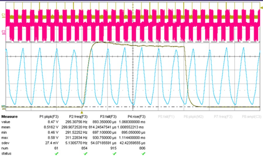
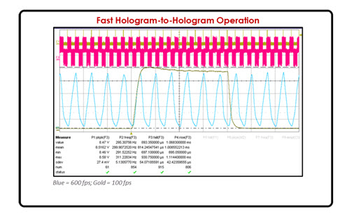
Maximum GS Hologram Frame Rate at 1064 nm: 600 fps(1000 fps available at reduced efficiency)
Trigger Response for On-board Holograms: 6 µs latency / 3 – 9 µs jitter
Graphs & Figures
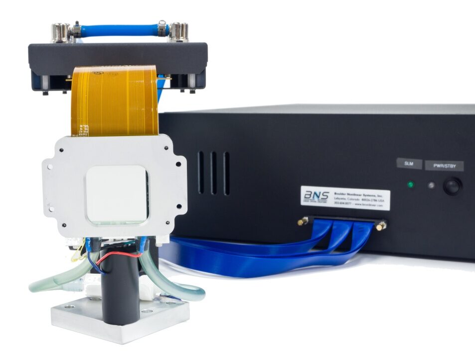
1536 x 1536 Spatial Light Modulator
The High-Speed 1536 x 1536 Spatial Light Modulator (SLM), combining high pixel count and high frame rate with efficient diffraction. By building on success with other models, the 1536 x 1536 SLM leverages the same pixel design in a reduced array size format for even faster addressing. The 1536 x 1536 SLM is built for speed. It uses large high-voltage, high-capacitance pixels which are essential for increasing switching speed. These factors also serves to reduce fringing field effects and phase ripple to improve photostimulation efficiency, especially at large diffraction angles. To optimize performance, the entire SLM head is thermally controlled for operation at elevated temperatures.
READ MORE
Common Specifications
Pixel Count: 1536 x 1536
Array Size: 30.7 mm x 30.7 mm
Pixel Pitch: 20 µm x 20 µm
Pixel Voltage: 12 V
Fill Factor: 96%
Maximum GS Hologram Frame Rate at 1064 nm: 600 fps(1000 fps available at reduced efficiency)
Trigger Response for On-board Holograms: 6 µs latency / 3 – 9 µs jitter
Ordering Information – Contact Us